Early Harley-Davidson Patent Drawings and Mechanical Innovations
These mechanical drawings were submitted to the United States Patent Office as Harley-Davidson worked through the practical problems of building a stronger, smoother and easier-to-use motorcycle. Together, the 21 retained sheets show engineers breaking the machine into crankshafts, valves, gears, frames, fork springs, stands, guards, tanks and saddles, then trying to improve each part.
What the Drawings Reveal
A patent drawing is not the same thing as a production blueprint. It records the arrangement an inventor asked the government to protect, and its numbered parts make sense only when read with the written specification and claims. A granted patent establishes that the application passed through the patent process; it does not, by itself, prove that every feature immediately appeared on a production motorcycle.
Even with that limitation, the drawings provide a close look at the mechanical questions occupying early motorcycle engineers. Photographs taken inside the Milwaukee assembly operation, at Indian’s Springfield factory, in Lewis's Adelaide machine shops, and at Vincent's Stevenage works show how design decisions became parts and complete motorcycles.
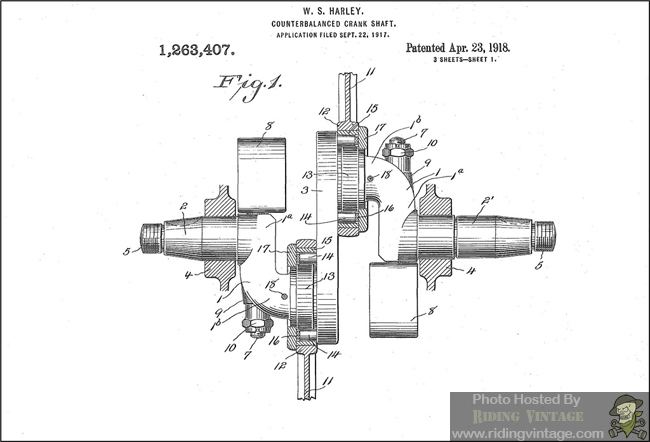


William S. Harley filed the counterbalanced-crankshaft application on September 22, 1917, and US Patent 1,263,407 was granted April 23, 1918. The patent proposed a one-piece crankshaft with detachable counterweights intended to offset part of the engine’s reciprocating load while still allowing one-piece connecting rods and bearing races to be assembled.
The patent should not be read as proof that Harley-Davidson adopted this exact crank arrangement throughout its production line. It does show that smoother operation, crankshaft rigidity and serviceable bearing assembly were already being treated as related design problems.
Packaging the Engine, Clutch and Transmission
The next three sheets belong to William S. Harley’s “Combined Engine Shaft, Clutch, and Transmission,” issued April 17, 1923.


The sectional views treat the clutch, shafts, gears and shifting controls as one packaged mechanical system. That approach reduced the distance between separate design problems: the engine had to transmit power, the clutch had to interrupt it, and the gear train had to provide selectable ratios within a compact housing.
Starting a Large Engine Without Fighting It
US Patent 1,301,256, filed September 19, 1917 and granted April 22, 1919, described a compression-relieving mechanism in the exhaust-valve operating system. During starting, the exhaust valves could be opened and held off their seats; when the mechanism was released, its parts returned to an inactive position for normal operation.


The practical object was straightforward: make the engine easier to turn through compression and reduce the chance of the starting mechanism kicking back. It was a starting aid, not a device intended to alter combustion while the motorcycle was being ridden.
Keeping Valve Timing Stable as the Engine Heated
US Patent 1,472,068, filed April 25, 1919 and granted October 30, 1923, addressed the different ways engine parts changed dimension as they warmed. The patent proposed aluminum cylinders and aluminum pushrods with the same coefficient of expansion, then surrounded the pushrods with housings formed integrally with the cylinders so both would remain at substantially the same temperature.

By correlating the temperature and expansion of the cylinders and pushrods, the arrangement was intended to preserve valve timing as the engine heated. Figure 1 shows the complete V-twin partly in section, while the smaller sectional detail shows the wall shared by a cylinder and its pushrod housing.


These three cropped sheets preserve additional engine and valve-gear sections showing casting shapes, fastener locations, valve pockets, passages and the way components were expected to fit together.
Selected Early Harley-Davidson Patent Milestones
The five patent summaries below provide a chronological framework. Filing and grant dates are kept separate because several applications remained pending for years.
US 1,263,407 — Counterbalanced Crank-Shaft
Inventor: William S. Harley
Filed: September 22, 1917
Granted: April 23, 1918
Purpose: Use a one-piece crankshaft with detachable counterweights while permitting one-piece connecting rods and bearing races to be assembled.
US 1,301,256 — Compression-Relieving Mechanism
Inventor: William S. Harley
Filed: September 19, 1917
Granted: April 22, 1919
Purpose: Open and hold the exhaust valves during starting, then return the valve-opening mechanism to its inactive position.
US 1,510,937 — Motor Cycle
Inventors: William S. Harley and Adam Ziska Jr.
Filed: November 1, 1919
Granted: October 7, 1924
Purpose: Form a stronger and simpler motorcycle frame from complementary sheet-metal channel members instead of relying on numerous brazed tubular joints.
US 1,527,133 — Shock Absorber
Inventor: William S. Harley
Filed: December 4, 1920
Granted: February 17, 1925
Purpose: Bring additional spring sets into action as fork movement and shock intensity increased.
US 1,675,551 — Cycle Support
Inventors: William S. Harley and Arthur R. Constantine
Filed: June 5, 1925
Granted: July 3, 1928
Purpose: Provide a pivoting motorcycle support controlled by a spring, catch and notched retaining arrangement.
Suspension and a Graduated Response to Rough Roads
William S. Harley’s US Patent 1,527,133 describes an early springer fork. It proposed a shock-absorber arrangement with moving fork members and several spring sets under different initial compression. The lighter cushioning springs handled normal movement, while additional springs and bumpers came into action as travel and impact increased.

The staged arrangement was intended to provide a graduated response rather than asking one spring to manage every road condition. The patent also separated cushioning and rebound duties within the fork assembly.
A Compact Opposed-Cylinder Power Unit
US Patent 1,360,110, issued November 23, 1920, described a simply constructed, light and compact opposed-cylinder engine for motorcycles. Its crankcase also incorporated a selective-speed transmission, bringing the engine and gearbox into one closely packaged power unit.

The patent also addressed valve actuation and a crankcase filler-cap arrangement, but the larger idea is visible in Figure 1: engine, clutch and selectable gearing were treated as one compact assembly. The drawing documents the proposed construction; it does not, by itself, establish production use.
Saddles, Stands, Guards and Other Practical Systems
Not every useful patent involved combustion or power transmission. A motorcycle also had to support its rider, stand securely when parked, protect itself and its operator, carry oil and electrical equipment, and present a recognizable shape.

The saddle patent addressed the supporting structure beneath the rider rather than engine performance.

The cycle-support detail sheet shows the pivot, spring and catch that controlled the stand’s stored and deployed positions.

The front-end drawing is a design patent rather than a utility patent. It protects the ornamental appearance shown in the figures, while the utility patents around it describe claimed functional arrangements.

The 1934 protecting-guard patent concentrated on the tubular guard and its attachment to the motorcycle frame.
Returning to the Front Fork

This complete motorcycle view places the staged-spring shock absorber from US Patent 1,527,133 in its intended front-fork location.

The 1938 oil-tank and battery patent dealt with packaging two essential systems in the limited space above the rear mudguard.

The final sheet returns to US Patent 1,675,551 and shows the cycle support on the complete motorcycle, beneath the footboard area.